Modeling A Crank-and-Slider Mechanism in Blender
The Problem
A crank-and-slider mechanism is a basic mechanism in which a wheel moves a rod connected to a linear sliding part. This is used to turn rotational motion into linear motion, and is similar to a piston-and-wheel mechanism, which turns the linear motion of the piston into the wheel's rotation. Think about steam trains.
When I tried to model this mechanism in Blender, what I found was lots of questions about it, some very contrived ways to do it using old Blender UIs, and some blender files that solved it, but I couldn't figure out easily how.
It's actually not that complicated, so I thought I'd contribute back to the Internet with a step-by-step tutorial on how to do this. Note that both mechanisms are the same as far as animation goes.
My Solution
All I'm showing here is modeling the armature. You can then attach your mesh geoemtry the usual way.Step one: New armature and crank bone
Go in to the correct ortho view (top, right, or front, depending on your geometry), and create a new armature with a single bone Shift-A > New Armature > Single Bone. I am using right view and the crank originates at the scene center. Tab into Edit Mode, go to the Bone panel in the Properties window and rename this bone to "Crank".
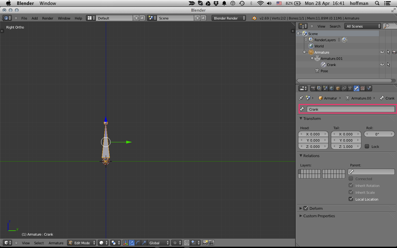
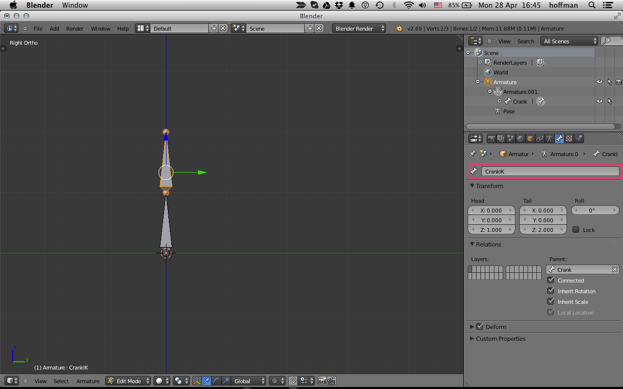
Create another bone by extracting this bone in Edit Mode E, and name this bone CrankIK. You can easily make it straight by manually setting the direction and length of the bone E > Z > 1 for example.
Step two: Add the rod bone and stretch helper
Still in edit mode, deselect all, and add another bone Shift-A. Move it to the side and name it "SliderStretch". It's easiest to select it in the Outliner to move it. Make it face the origin of the Crank bone. Then E extrude it, and name the next bone "Rod". I made the rod just about 150% longer than the Crank, but it's up to your model.
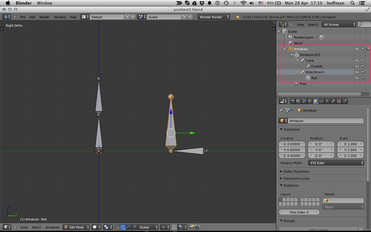
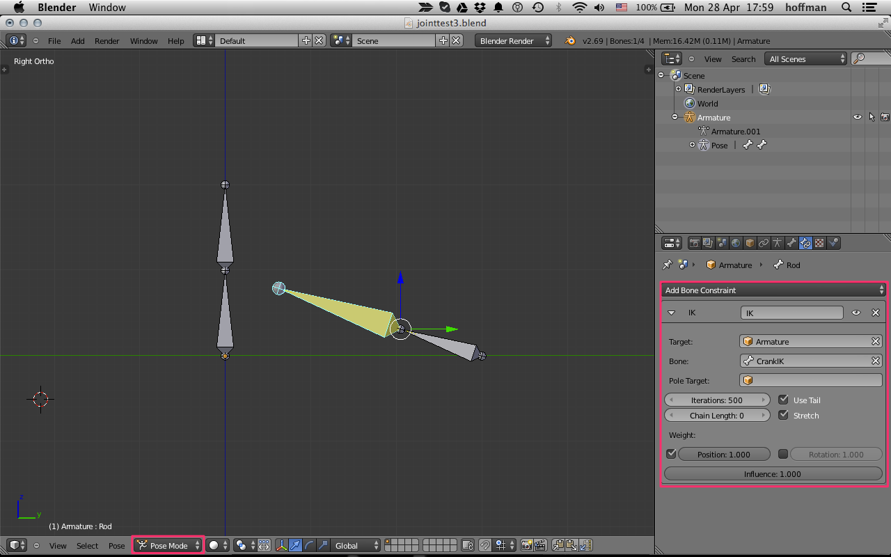
Go to Pose mode, and with the Rod bone still selected, add an "Inverse Kinematics" bone constraint, with the CrankIK bone as the target. Make sure that Both "Use Tail" and "Stretch" are selected. Don't worry that the rod doesn't reach the crank yet. We'll fix it.
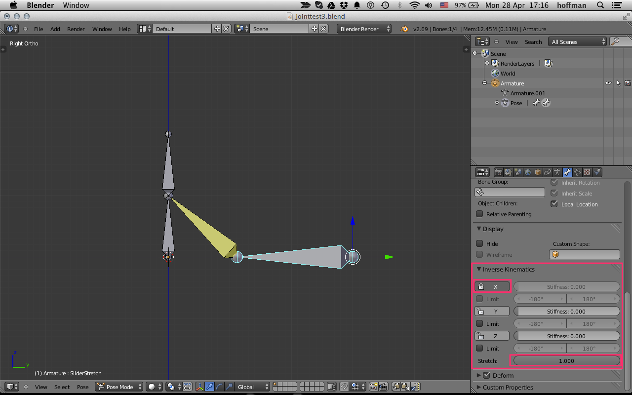
Still in Pose mode, select the SliderStrech bone and go to the "Bone" panel. There, open the Inverse Kinematics subpanel, and set "Strecth" to 1.0 and Limit the "X" rotation (or whatever rotation is appropriate in your model.
Step three: Add the slider bone
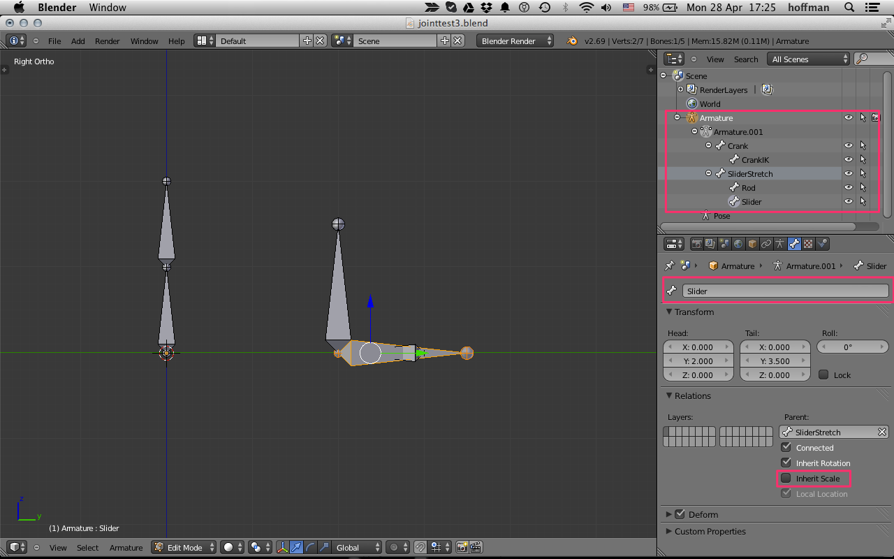
Theoretically, you're done. You might want to add a slider bone to the SliderStrech bone to animate your slider mesh. Do this by going back to edit mode, selecting the SliderStrech bone and E extracting another bone. I called it "Slider". Make sure to uncheck "Inherit Scale" from the bone properties window.
Go back to Pose mode, select the Crank bone and R rotate it. Enjoy!
Animation
Right-click > Open Image in New Tab to reload animation
2014. Guy Hoffman.